Where was it built?
Doncaster, England, in the United Kingdom.
It was built for the London and North Eastern Railway and designed by Nigel Gresley.
 RAIL ATLASby Train Life
4-6-2
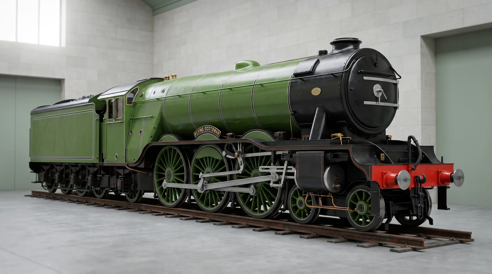
Flying Scotsman was built in Doncaster in 1923 and designed by Nigel Gresley. It took its name from the London–Edinburgh service. In 1934 it reached 100 mph on a special test run, earning a place in railway history.
Drag to turn · Pinch to zoom · Tap a number to explore
Heat turns water into steam. Steam pushes pistons, and rods turn the wheels. Explore the boiler, cab, running gear and supplies.
Hot gases pass through the boiler and into the smokebox before leaving through the chimney. Look underneath: a curved support called a saddle holds the front on the locomotive’s frame.
Built at Doncaster Works in 1923 to Nigel Gresley’s A1 design, later rebuilt as an A3. The model follows the apple-green 4472 appearance in the supplied photograph. Its 100 mph figure is from the 1934 test run, not a normal service limit.
The crew works here. On a conventional steam locomotive, the fireman tends the fire and the driver controls the engine.
A locomotive’s cab is a workplace, not a passenger compartment. Some early engines had little shelter for their crews.
The chimney carries exhaust away. Steam domes help collect steam above the water in the boiler.
Steam and smoke are different: steam is water vapour, while smoke comes from burning fuel. Equipment varies by locomotive.
Steam pushes pistons. Rods transfer that motion to the driving wheels, and coupling rods link driving wheels together.
Flying Scotsman has three cylinders: two outside and one between the frames. The model animates the visible outside rods; its hidden middle-cylinder mechanism and complete valve gear are not reconstructed. The four small leading wheels help guide the locomotive, while the six large driving wheels provide traction.
A steam engine needs water and fuel. Tank engines carry supplies on the locomotive; many other engines pull a tender.
The model shows the general storage area. Tender and tank capacities are not reproduced to engineering dimensions.
Doncaster, England, in the United Kingdom.
It was built for the London and North Eastern Railway and designed by Nigel Gresley.
Steam pushes pistons, and connecting rods turn the driving wheels.
The wheels grip the rails to move the train. Passenger engines and small yard engines have different jobs: maximum speed is not the only measure of a good locomotive.
Flying Scotsman was built in 1923.
It began service on 24 February 1923. Later rebuilds changed the engine; its history is longer than a single birthday.
Historically: the East Coast route between London and Edinburgh.
Today, preserved-railway visits and special trips can take it elsewhere. Its name originally belonged to the London–Edinburgh service.
It is a working heritage locomotive, with special visits and trips.
The museum lists 2026 events. It no longer runs a normal daily express service; maintenance and the event schedule determine when it can run.
Fleet-status check: 2026-09-17. Consult the operator for departures.We leave gaps visible instead of guessing. The original catalogue and our learning model do not establish every real-world specification.
A train uses different materials for different jobs: metals for strength, glass for windows and insulating materials around wires. Paint colour cannot tell us whether the body underneath is steel or aluminium.
Follow these steps, then find the matching sections in the model above.
Burning fuel supplies heat.
Heat turns water into steam.
Steam pushes; rods transfer the motion.
The wheels grip the rails.
4-6-2 uses wheel counts: 4 leading wheels, 6 driving wheels and 2 trailing wheels. Count both sides together. A T means tank engine; ST means saddle tank and WT means well tank.
Historic test run · 100 mph. A maximum speed describes particular conditions; station stops, curves, signals and track limits make an actual journey slower.
A fast train is a whole system: vehicle, track, electricity or fuel, brakes, signalling and trained people. A race in the game is a simplified comparison.
No. Smoke comes from burning fuel. Steam is water in its gas form. The white cloud you can see contains tiny water droplets formed as water vapour cools.
No steering wheel is needed to choose a direction. The rails guide the wheelsets. At a junction, movable sections of rail called points or switches guide the train onto another track. The driver controls speed and braking.
A moving train has energy. Brakes must remove that energy to slow it down. A heavy train travelling fast needs room to stop, so railway signals help keep trains safely separated.
Compare how they look, what they carry and where their power comes from.
A frame holding wheelsets beneath a vehicle. It can turn relative to the body to help the train follow curves.
The distance between the inside faces of the two running rails. Narrow gauge means closer rails; loading gauge describes the space a train may occupy.
A folding roof collector that stays in contact with an overhead power wire.
The force used to pull or propel the train. Grip between wheels and rails limits how much force can be used.
A train with propulsion equipment within its passenger vehicles, operated together from one cab.
A powered vehicle whose main job is to move other railway vehicles.
Moving and arranging vehicles in a yard, often at low speed.
The colours, stripes, logos and other markings painted or applied to a train.
The permitted speed for passenger or freight operation on a suitable section. It is not the journey average.
A speed achieved on a particular test or record attempt, sometimes with special equipment and conditions.
A vehicle coupled to a steam locomotive to carry extra water and fuel. A tank engine carries water on the locomotive itself.
An early vehicle built to develop and test a design before a production fleet.
Follow the operator, builder and museum references below for more detail. Links beside an answer show which source supports that answer.
Edition 2026-09-27. Catalogue background is carried forward from the original collection; it is not a new independent verification. Engineering explanations describe principles. Portraits and 3D models are illustrations, with simplified parts and proportions. This is an independent learning guide, not an operator’s timetable.
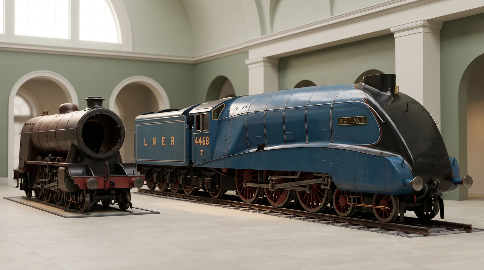 LNER A4 Mallard
 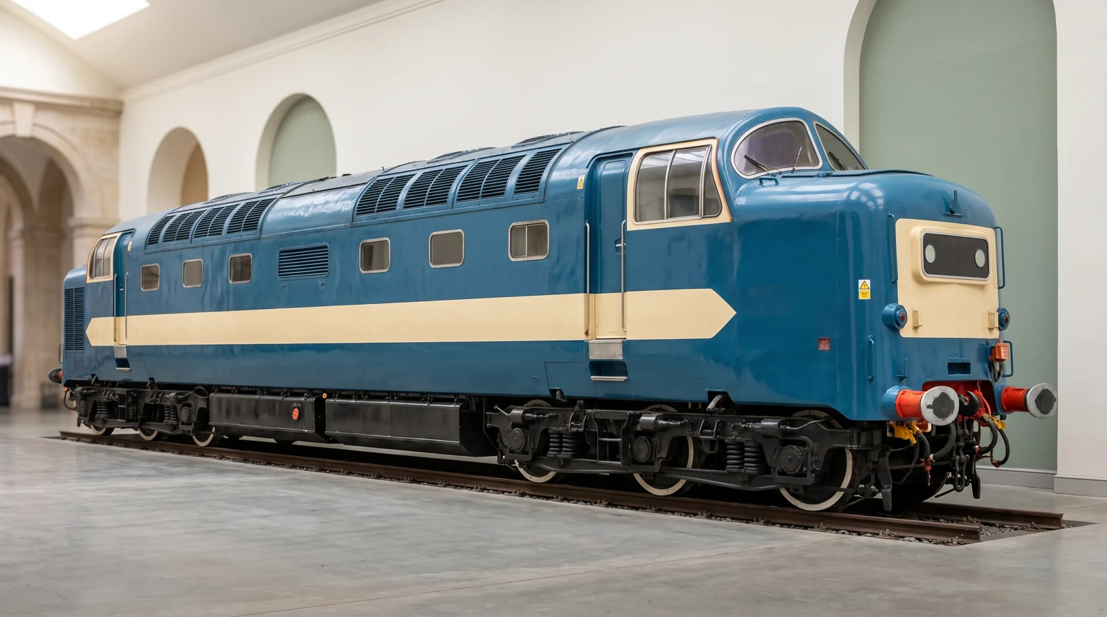 English Electric DP1 Deltic
 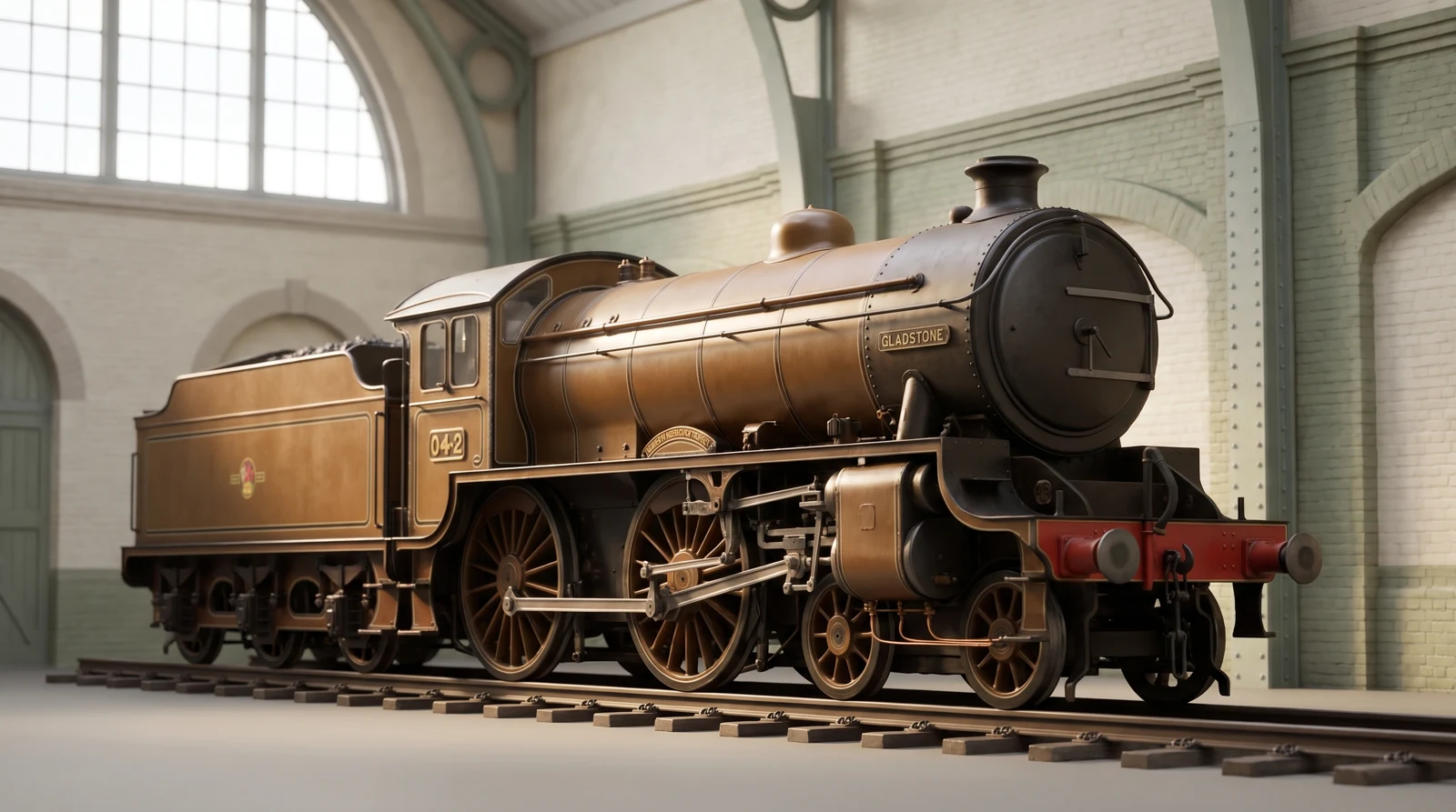 LB&SCR B1 Gladstone